A arduino library for the MAX7221 and MAX7219
These two chips provide an easy way to control either an array of 64 Led's or up to eight digits made of 7-segment displays with a minimum of electronic components. Besides the chip itself you will need only a single resistor and one or two capacitors. Data is send to the chip using a SPI-compatible protocol using 3 of the digital pins on the arduino. If you want control more than eight 7-segment displays (or more than 64 Led's) the chips can be cascaded. The library supports up to 8 cascaded devices, which add up to 512 Led's that can be lit individually. The good news is that you still need only 3 pins on your arduino board.
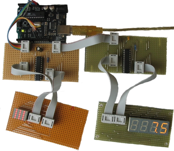
Here is a picture of my rather crappy (but working) testbed...
Everything else you need to know about the MAX7221 and MAX7219 is to be found in the components datasheet. I will refer to the datasheet in various places when describing the library functions. So I would suggest you read it before going on...
Table of Contents
The LedControl library
This is not the first time someone puts out code for the arduino and the MAX7221, but the focus has usually been on controling Led's layed out in some kind of rectangular matrix. I mainly use the chips to drive 7-segment displays, so I obviously want a function to display numbers (decimal and hexa-decimal) and also the limited set of alphanumeric characters that make (visual) sense for these types of displays.
I also wanted the code to be useful for a bigger audience, so there had to be a set of functions to switch individual or groups of Led's on and off.
If you have used other libraries for the MAX72XX that used the Sprite-library, I have to tell you that the LedControl-library does not support Sprites, mainly because the library uses too much memeory on the Arduino. Adding the LedControl-library to your code will cost you 1690 bytes on an ATMega168. But this number is for the basic (do-nothing) application, where we only include the library-code without calling any of the functions.
//This app does nothing but waste (library-)memory
#include "LedControl.h"
void setup() {}
void loop() {}
In my environment (arduino0007 on linux) memory consumption for the compiled application
is raised from 4070 bytes (with the #include-statement commented out)
to 5760 from the code above. This is a little bit less than using the combination
of the Matrix/Sprite-library that adds 2266 bytes to my code. (I actually have been wondering
for some time now where that memory is burned inside the Sprite-library. Sprite.h alone
is reponsible for 1.2 kB of the 2.2 kB gone ...?)
If you have been using the Matrix/Sprite-lib you will not be amused to hear this one :
The LedControl-lib uses a different scheme of adressing the individual Led's on the hardware
Ok, I know that this is annoying, but it should not be difficult to port an existing application
with the hints given later on. The reason I use a different hardware-address scheme for the Led's,
is that the layout used in the Matrix/Sprite-lib would require some extra bit-twisting code
for each change on an Led's state. Since you will have to rewrite all of your code anyway when switching
librarys, I decided to put that extra burdon upon you, just to save some more bytes and performance, sorry.
Other differences between existing library-code and the LedControl-lib are discussed
along with the API-documentation.
Creating a LedControl
All the libraries API-functions are called through an variable of type LedControl.
Lets go right into some basic code :
/* we have to including the library */
#include "LedControl.h"

/*
 * Create a new LedControl.
 * We use pins 12,11 and 10 for the SPI interface
 * With our hardware we have connected pin 12 to the DATA IN-pin (1) of the first MAX7221
 * pin 11 is connected to the CLK-pin(13) of the first MAX7221
 * pin 10 is connected to the LOAD-pin(12) of the first MAX7221
 * We will only have a single MAX7221 attached to the arduino
 */
LedControl lc1=LedControl(12,11,10,1);
The first step is is obvious we have to include the LedControl-library. Then we create
an instance of type LedControl to talk to the MAX7221 devices. An LedControl is to be
initialized with 4 arguments. The first 3 arguments are the pin-numbers you haved used
in the connection between the arduino-board and your (first) MAX72XX. You are free to choose
any of the digital IO-pins on the arduino, but some of the pins are used also for serial
communication with other devices or have a led attached to them (happens to be on pin 13 of my board).
In the example I choose pins 12,11 and 10. But this simply depends on your own hardware setup.
The library does not check for the pin-numbers to be valid in any way. Passing in something stupid
will break your app.
You don't have to set the pins to be used for the devices as outputs or initialize them in any way. The library handles all this for you. Simply hand them over to constructor and then leave them alone for the rest of the code.
Besides the 3 pin-numbers you provide the number of cascaded MAX72XX devices you will
be using on this SPI-Bus. The LedControl-lib allows to address up to 8 devices
from a single LedControl-variable. There is a little performance penalty implied with
each device you add to the chain. If that is not important to you (try it out in your code) you could
simply go for the maximum (8) devices. The library always uses the same amount of memory, no matter
how many devices you set in the argument. Only values between 1..8 are allowed here, otherwise
the default of 8 devices is used.
Here is the prototype for a new LedControl-instance:
/*
 * Create a new controler
 * Params :
 * int dataPin    The pin on the Arduino where data gets shifted out
 * int clockPin   The pin for the clock
 * int csPin      The pin for selecting the device when data is to be sent
 * int numDevices The maximum number of devices that can be controled
*/
LedControl(int dataPin, int clkPin, int csPin, int numDevices);
If you need to control more than 8 MAX72XX, you'll have to create
another LedControl-variable that uses 3 other Pins on your arduino-board.
/* we have to include the library */
#include "LedControl.h"

// Create a new LedControl for 8 devices...
LedControl lc1=LedControl(12,11,10,8);

// ... and another one, now we control 1024 Leds's from an arduino, not bad!
// The second one must use different pins!
LedControl lc2=LedControl(9,8,7,8);
Obviously two instances of LedControl cannot share the pins on the arduino-board.
There are no functions to replace or swap any of the pins later on. You can't even read
the used pin-numbers from your code. All this depends very much on the hardware you
build, so implementing functions for this would be a waste of memory.
But a function by which you can request the maximum number of devices attached
to an LedControl can be very handy when you want to iterate over the full
list of MAX72XX devices attached to an LedControl.
Here is a piece of code that switches all of the MAX72XX-devices from power saving mode
into normal operation. I'll think you'll get the idea even though we haven't talked
about the shutdown() function yet...
#include "LedControl.h"

// Create a new LedControl for 5 devices...
LedControl lc1=LedControl(12,11,10,5);

void setup() {
  for(int index=0;index<lc1.getDeviceCount();index++) {
      lc1.shutdown(index,false);
  }
}
We iterate over the list of devices by an index that runs from 0 to getDeviceCount()-1.
(That would be 0 to 4 in this piece of code.) The index is the address of each device. This address
will be the first argument of every function that sets a feature or a new (Led-)value on a device.
Keep in mind that getDeviceCount() returns the number of devices attached, but the address of an device
starts at 0 for the first one, 1 for the second one,.. getDeviceCount()-1 for the last one.
Here is the prototype of the function:
/*
 * Gets the maximum number of devices attached to this LedControl.
 * Returns :
 * int   the number of devices attached to this LedControl
*/
int LedControl::getDeviceCount();
Power saving mode
Led's consume quite a lot of energy when lit. For battery operated devices you'll definitly want to save power by switching the whole display off, when the user does not need it. A special command sequence can put the MAX72XX into shutdown mode. The device will switch off all the Led's on the display, but the data is retained inside the chip. You can even continue to send new data to the device when shutdown mode active. The data is processed even though the display is switched off. As your code pulls the device out of shutdown mode later you will see the updated Data on your Display. Here is an example for an invisible countdown:
//create a new device
LedControl lc=LedControl(...);

//Here is an invisible countdown
int i=9;
//print that to the display
lc.setDigit(0,(byte)i,false);
//well see the number '9'
delay(1000);
//now switch the display off ...
lc.shutdown(true);
//and count down invisibly
while(i>1) {
    lc.setDigit(0,(byte)i,false);
    i--;
    delay(1000);
}
//when we switch the display on again it will show '1'
//which was updated during shutdown
lc.shutdown(false);
lc.setDigit(0,(byte)i,false);
Here is the prototype for method LedControl.shutdown()
/*
 * Set the shutdown (power saving) mode for the device
 * Params :
 * int addr   The address of the display to control
 * boolean b  If true the device goes into power-down mode. If false
 *            device goes into normal operation
*/
void shutdown(int addr, bool b);
Please note that the MAX72XX is always in shutdown mode when the arduino is powered up.
Device initialization
In the datasheet for the MAX72XX you'll find a chapter about the power up settings of the devices. The library uses (almost) the same settings:
- the display is blanked
- the device does not decode the data send to it
- the intensity is set to the minimum
- the device starts up in shutdown (power saving) mode
- the maximum number of digits on the device is activated
Starting up in power saving mode is always a good idea for an battery operated application,
but you will have to activate every device before use. If you go back to the code-example in
section Power saving mode you'll see how this is done inside the
setup() function of your application.
Please do note that (different from the default hardware-setup of a MAX72XX) the library activates the maximum number of digits (8) on the device (see ScanLimit())
Limiting the number of digits
When a new LedControl is created it will activate all 8 digits on the display of all the devices. So each lit digit will be switched on for 1/8 of a second by the multiplexer that drives the digits. If you have any reason to limit the number of scanned digits, this is what happens : The Led's get switched on more frequently, and therefore will be on for longer periods of time. Setting the scan limit to 4 would mean that a lit Led is now switched on for 1/4 of a second, so the MAX7221 has to provide the current on the segment-driver for a longer period of time.
Make sure you read the relevant section of the datasheet on this topic, because it
is actually possible to kill your MAX72XX by choosing a bad combination of the resistor that
limits the current through the Led's and the number of digits scanned.
The only reason to tweak the scanlimit at all, is that the display looks too dark. But this
is most likely caused by the fact that you haven't raised the intensity on startup.
Here's the prototype for setScanLimit():
/*
 * Set the number of digits (or rows) to be displayed.
 * See datasheet for sideeffects of the scanlimit on the brightness
 * of the display.
 * Params :
 * int addr  The address of the display to control
 * int limit The number of digits to be displayed
 * Only values between 0 (only 1 digit) and 7 (all digits) are valid.
 */
void setScanLimit(int addr, int limit);
Setting display brightness
There are three factors that determine the brightness of the display. The first one
is the resistor Rset which limits the maximum current through the Led's. The datasheet
has a section on selecting a proper value for Rset. If its too small there is a chance the
Led's draw more current than the MAX72XX can handle.
The second factor to display brightness is the scan limit of the display. From the ScanLimit section you already know that I'd recommend to leave that parameter at its safe default.
But display brightness can be software controled too, and this is what you should use.
The lower and upper boundries are set by the hardware (i.e. Rset and ScanLimit) but the
setIntensity() method allows you to control brightness in a wide range. There are just
a few things to keep in mind:
- When the MAX72XX is powered up the brightness is set to its darkest value. So you want to raise the intensity from your code to something brighter. (But : if you don't see anything ... did you read the section on power saving?)
- Lowest intensity does not mean the display isn't lit at all, its simply : dark!
- The range of values is from 0(dark) to 15(brightest). Every other value will be ignored.
Here is the prototype for this method:
/*
 * Set the brightness of the display.
 * Params:
 * int addr      the address of the display to control
 * int intensity the brightness of the display.
 *               Only values between 0(darkest) and 15(brightest) are valid.
*/
void setIntensity(int addr, int intensity);
Clearing the display
What can be said on this topic once you read the name of
the method : LedControl.clearDisplay()?
/*
 * Switch all Leds on the display off.
 * Params:
 * int addr The address of the display to control
 */
void clearDisplay(int addr);
All Led's off after this call, that's it...
Controling a Led matrix
Ok, I made this one up. But with 7 MAX72XX it could actually be done...
The picture of my setup at the top of the article reveals that I have only single 5x7 Matrix Led array.
With this Matrix I'm not even able to use the full 8x8 Matrix that could be controled with a MAX72XX.
But this cheap display is ok for testing the basic concepts the LedControl library
provides for a Led matrix.
There are 3 different functions for switching a Led in a Matrix on and off. We start with a function that lets you control each of the Led's individually...
Lighting up a single Led
Here is the prototype for the function
/*
 * Set the status for a specific Led.
 * Params :
 * int addr  the address of the display to control
 * int row   the row in which the led is located
 *           Only values between 0 and 7 are valid.
 * int col   the column in which the led is located
 *           Only values between 0 and 7 are valid.
 * boolean state If true the led is switched on, if false it is switched off
 */
void setLed(int addr, int row, int col, boolean state);
It should be obvious what the function does and what the
addr and the state arguments stand for. But what
is meant by a row and a column on the matrix?
As the idea of the Leds layed out in the shape of matrix is a purely theoretical one, here is a schematic that should clarify how the matrix is to be connected to the pins of an MAX72XX.
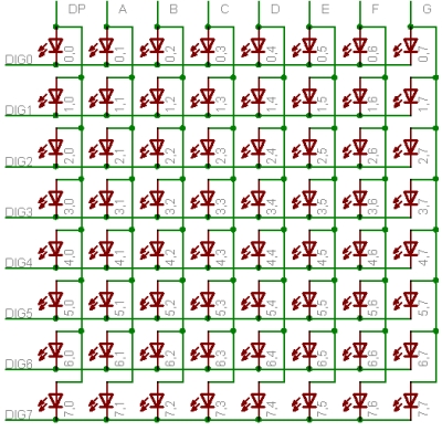
//switch the led in the third row (index 2) eighth column (index 7) on
lc.setLed(0,2,7,true);
delay(500);
lc.setLed(0,2,7,false);
Lighting up a row or column on the matrix
If you have to set the change the status of several Led's at once,
it would blow up your code to use setLed() for each Led
to switch on or off. But there are two more functions
that set the value of either a row or a column in the matrix.
With setLed() a boolean value was enough to signal the desired status of the Led.
But now we want to update 8 Leds with a single function call, so the status of the
individual Led's needs to be encoded somehow.
Here again is the schematic of our LedMatrix but now I have added the values to be
set for each lit Led on a row or column.
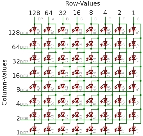
| Led 2.0 | Led 2.1 | Led 2.2 | Led 2.3 | Led 2.4 | Led 2.5 | Led 2.6 | Led 2.7 | ||
|---|---|---|---|---|---|---|---|---|---|
| On | Yes | No | No | Yes | No | No | Yes | No | |
| Row-Value | 128 | 0 | 0 | 16 | 0 | 0 | 2 | 0 | =146 (128+16+2) |
In your code you would use lc.setRow(0,2,146) to set this row on the first MAX72XX
attached to the arduino.
The setRow()-call works also much faster than calling setLed() in turn for each
Led. So use this one whereever you can.
What can be done for rows can also be achieved with columns. The setColumn() method
does the same thing for the vertical columns in the schematic.
In the sixth column (remember index = 5) we want the 4 leds at the bottom to be lit. A table
for the value to be passed into setColumn() would look like this
| Led 0.5 | Led 1.5 | Led 2.5 | Led 3.5 | Led 4.5 | Led 5.5 | Led 6.5 | Led 7.5 | ||
|---|---|---|---|---|---|---|---|---|---|
| On | No | No | No | No | Yes | Yes | Yes | Yes | |
| Column-Value | 0 | 0 | 0 | 0 | 8 | 4 | 2 | 1 | =16 (8+4+2+1) |
We'll end this section with the prototypes for both functions
/*
 * Set the 8 Led's in a row to a new state
 * Params:
 * int addr   The address of the display to control
 * int row    The row on which the led's are to be set
 *            Only values between 0 and 7 are valid.
 * byte value A bit set to 1 in this value will light up the
 *            corresponding led.
 */
void setRow(int addr, int row, byte value);

/*
 * Set the 8 Led's in a column to a new state
 * Params:
 * int addr   The address of the display to control
 * int col    The column on which the led's are to be set
 *            Only values between 0 and 7 are valid.
 * byte value A bit set to 1 in this value will light up the
 *            corresponding led.
*/
void setColumn(int addr, int col, byte value);
Controling 7-segment displays
This is going to be much easier than the last section. The picture at the very top of this page already showed what is possible. I think there is no need for a schematic here, beause from the datasheet of the MAX72XX it should be quite clear how 7-segment displays are to be wired.
Display dezimal (or hex) numbers
The first function takes a byte-value argument and prints it as the corresponding number to the specified digit on a display. The range of values runs from 0..15. Values between 0 and 9 are printed as numbers, for values between 10 and 15 the hexadecimal character is printed. All other values will simply be ignored. Ignored in this case means, nothing will be printed. The digit will not be blanked, it will simply retain its last valid value. The decimal point for the digit is handeled by another argument that lets you switch the DP-Led on or off. Here is a litte example that prints an int value to a display with (at least) 4 digits. (It uses a call explained from the next chapter for the sign extension):
void printNumber(int v) {
    int ones;
    int tens;
    int hundreds;
    boolean negative;

    if(v<0) {
        negative=true;
        v=v*-1;
    }
    ones=v%10;
    v=v/10;
    tens=v%10;
    v=v/10;
    hundreds=v;
    if(negative) {
       //print a minus on the first MAX72XX, 4'th digit from the right, no decimal-point
       lc.setChar(0,3,'-',false);
    }
    else {
       //print a blank in the sign column
       lc.setChar(0,3,' ',false);
    }
    //Now print the number digit by digit
    lc.setDigit(0,2,(byte)hundreds,false);
    lc.setDigit(0,1,(byte)tens,false);
    lc.setDigit(0,0,(byte)ones,false);
}
The prototype for the function looks like this:
/*
 * Display a hexadecimal digit on a 7-Segment Display
 * Params:
 * int addr   the address of the display to control
 * int digit  the position of the digit on the display
 * byte value the value to be displayed.
 *            Only values between 0x00 and 0x0F are valid.
 * boolean dp If true also switches on the decimal point.
 */
void setDigit(int addr, int digit, byte value, boolean dp);
The digit-argument can be from the range 0..7 because
the MAX72XX can drive up to 8 7-segment displays and the index starts
at 0 as usual.
Displaying characters
Although only a limited set of characters can be shown on a 7-segment display, this is
sometimes very handy. The value argument is of type char and can be from the range
(numeric)0 to numeric(127). For all these value we have a defined character which is
mostly the <SPACE>. But if there is a recognizeable representation for a (ASCII-)character
it will be printed to the display. For character values above 127 the <SPACE> character
will be printed.
Here is the set of printable characters:
0 1 2 3 4 5 6 7 8 9A a(prints upper case)B b(prints lower case)C c(prints lower case)D d(prints lower case)E e(prints upper case)F f(prints upper case)H h(prints upper case)L l(prints upper case)P p(prints upper case)-(the minus sign).,(lights up the decimal-point)_(the underscore)<SPACE>(the blank or space char)
For conveniance reasons the hexadecimal characters have also been redefined at the char values 0x00...0x0F. For that reason you can simply pass in a byte instead of a char argument if you want to mix digits and characters on the display. The prototype of the function is almost the same as the one for displaying digits.
/*
 * Display a character on a 7-Segment display.
 * The char that can be acutally displayed are obviously quite limited.
 * Here is the whole set :
 * '0','1','2','3','4','5','6','7','8','9','0',
 * 'A','b','c','d','E','F','H','L','P',
 * '.','-','_',' '
 * Params:
 * int addr   the address of the display to control
 * int digit  the position of the character on the display
 * char value the character to be displayed. (See the limited set above!)
 * boolean dp If true also switches on the decimal point.
*/
void setChar(int addr, int digit, char value, boolean dp);
Ok, that was it ... thanks for listening!
Download
The file LedControl.zip contains the sourcecode for the library and a local version of this documentation. The zip-file will create a new directory named LedControl with the following contents:
- LedControl/LedControl.h The header to be included into your project
- LedControl/LedControl.cpp The implementation
- LedControl/doc/LedControl.html The html documentation
- LedControl/doc/lc.css The stylesheet for the html documentation
- LedControl/doc/*.jpg Several pictures used in the html documentation
You have to unpack the zip-file into the library directory of your arduino environment. The location of the library directory has changed with more recent versions of the arduino environment.
- If you are running a version from
0007up to0009the libraries are located atarduino-<version>/lib/targets/libraries/ - Version
0010expects libraries to be installed atarduino-<version>/hardware/libraries/
After LedControl.zip has been unpacked into the directory from above, the new library has to be compiled.
From the arduino-ide this is very simple:
Create a new sketch with the following content:
#include "LedControl.h"

void setup() {}
void loop() {}
Now hit the verify/compile button and the library will be compiled and
is then available for all of your sketches that start with a #include "LedControl.h
line.
Known bugs
When the library gets compiled inn the arduino-ide, some warnings are issued. None of these warnings is relevant for your application code.
There is more to come surely!
Revision History
June 23, 2007 First public release
Feedback
Your first stop should be the arduino forum section Hardware/Interfacing
which I visit regulary. But you are also welcome to send questions,
objections or corrections to <e.fahle@wayoda.org>
License (The software)
The sourcecode for this library is released under the Terms of the GNU Lesser General Public License version 2.1.
License (This document)
This document is ©2007 by Eberhard Fahle. I make no claims as to the completeness or correctness of the information contained in this document. Permission is granted to copy, distribute and/or modify this document under the terms of the GNU Free Documentation License, Version 1.2 or any later version published by the Free Software Foundation; with no Invariant Sections, no Front-Cover Texts, and no Back-Cover Texts.